Toyota Avalon XX10 (1995-1999) Torque Spec Settings
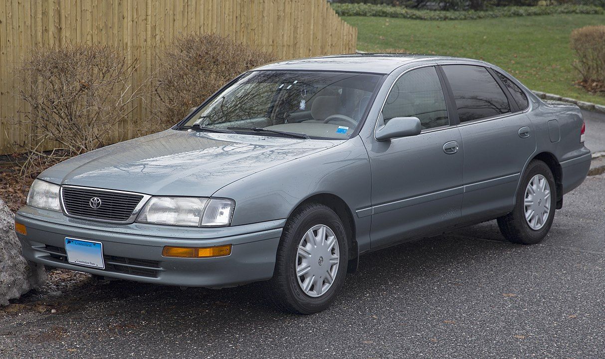
Mr.choppers, CC BY-SA 3.0, via Wikimedia Commons
Below you'll find the tightening torques for the Toyota Avalon XX10 in both Nm and ft/lbs. The first table contains the most-used torque settings. The tables after it contain all torque spec values I could find.
Most-used torque specs for Toyota Avalon XX10
| Part | Description | Torque (Nm) | Torque (ft/lbs) | Remarks | Applies to | |
|---|---|---|---|---|---|---|
| Spark plugs | Spark plugs | 18 | 13 | Use 16mm plug wrench. |
|
|
To make sure these are the correct tightening torque values, you can use the data below to verify this is the right model.
Are these torque settings right for you?
- Production years: 1995 - 1999
- Generation: 1st
- Type of van: car
- Model variant: Base
All Torque Settings in Tables
engine torque settings
Save to email ✉️| Part | Description | Torque (Nm) | Torque (ft/lbs) | Remarks | Applies to | |
|---|---|---|---|---|---|---|
| Oil pan | No. 1 oil pan (10mm head bolt) | 8 | 6 |
|
|
|
| Oil pan | No. 1 oil pan (12mm head bolt) | 19.5 | 14 |
|
|
|
| Oil pan | No. 2 oil pan bolts | 8 | 6 | Apply seal packing: Part no. 08828-00080 or equivalent. |
|
|
| Oil pan | Oil hole cover plate to No. 2 oil pan | 8 | 6 |
|
|
|
| Oil pan | No. 1 oil pan bolts to transaxle | 37 | 27 |
|
|
|
| Oil pan | No. 2 oil pan bolts to transaxle | 46 | 34 |
|
|
|
| Oil pan | RH drain plug | 7 | 5 |
|
|
|
| Oil pan | LH drain plug | 13 | 10 |
|
|
|
| Oil pan | Oil pan baffle plate | 8 | 6 |
|
|
|
| Oil filter | Oil filter union | 13 | 10 | Use 12mm hexagon wrench. |
|
|
| Oil filter | Oil strainer bolt | 8 | 6 | Install with new gasket, 1 bolt, and 2 nuts |
|
|
| Oil pressure switch | Oil pressure switch | 13 | 10 | Adhesive: Part no. 08833-00080. THREE BOND 1344, LOCTITE 242 or equivalent. |
|
|
| Oil dipstick | Oil dipstick and guide bolt | 8 | 6 |
|
|
|
| Oil pump | Oil pump (10mm head bolt) | 8 | 6 | Apply seal packing (part no. 08826-00080 or equivalent) to the oil pan |
|
|
| Oil pump | Oil pump (12mm head bolt) | 19.5 | 14 | Apply seal packing (part no. 08826-00080 or equivalent) to the oil pan |
|
|
| Oil pump | Relief valve | 36.8 | 27 |
|
|
|
| Piston rods | Connecting rod cap and lower bearing | 24.5 | 18 | Add 90°. Do not turn the crankshaft. |
|
|
| Cylinder head | Cylinder head cover bolts | 8 | 6 |
|
|
|
| Cylinder head | Cylinder head rear plate bolt | 8 | 6 |
|
|
|
| Cylinder head | Cylinder head (12 pointed head) bolts | 64 | 47 | Add 90° |
|
|
| Cylinder head | Cylinder head (recessed head) bolts | 18.5 | 14 | Apply light coat of engine oil on threads. Use 8mm hexagon wrench. |
|
|
| Cylinder head | LH delivery pipe bolt | 10 | 7 |
|
|
|
| Cylinder head | Pressure regulator bolts | 8 | 6 |
|
|
|
| Cylinder head | Thermal vacuum valve | 30 | 22 | Apply THREE BOND 1324 (or equivalent) to threads. |
|
|
| Spark plugs | Spark plugs | 18 | 13 | Use 16mm plug wrench. |
|
|
| Battery | Ignition coils | 18 | 13 | Install the 6 ignition coils to the RH and LH cylinder heads. |
|
|
| Intake manifold | Intake manifold assembly | 15 | 11 | Install with 9 bolts, 2 nuts, and 2 plate washers. |
|
|
| Intake manifold | Air intake chamber | 43 | 32 | Use 8mm hexagon wrench. Install with new gasket, 2 bolts, and 2 nuts. |
|
|
| Intake manifold | Air intake chamber stay bolts | 19.5 | 14 |
|
|
|
| Intake manifold | Intake air control valve | 14.5 | 11 | Install the intake air control valve and data link connector 1 clamp with 3 nuts. |
|
|
| Intake manifold | Ground stop to intake air control valve | 14.5 | 11 |
|
|
|
| Throttle body | Throttle body bolts | 19.5 | 14 |
|
|
|
| Engine mounts | No.1 engine hanger bolts | 39 | 29 |
|
|
|
| Engine mounts | No. 2 engine hanger bolts | 19.5 | 14 |
|
|
|
| Engine mounts | No. 2 engine mounting bracket | 63.7 | 47 |
|
|
|
| Engine mounts | Engine moving control rod | 63.7 | 47 |
|
|
|
| Engine mounts | RH engine mounting stay | 31.4 | 23 |
|
|
|
| Engine mounts | RR engine mounting insulator bolt | 65.7 | 48 |
|
|
|
| Engine mounts | FR engine mounting insulator bolt (TMC made) | 80.4 | 59 |
|
|
|
| Engine mounts | FR engine mounting insulator bolt (TMM made) | 65.7 | 48 |
|
|
|
| Engine mounts | LH engine mounting insulator bolt | 63.7 | 47 |
|
|
|
| Engine mounts | Engine mounting shock absorber | 48 | 35 |
|
|
|
| Sensor | Knock sensor 1 and 2 | 39 | 29 |
|
|
|
| Sensor | Mass air flow (MAF) meter | 6.9 | 5 |
|
|
|
| Sensor | Engine coolant temperature (ECT) sensor | 20 | 15 | Use 19mm deep socket. |
|
|
| Alternator | Drive belt adjusting bar bracket bolt | 25 | 18 |
|
|
|
| Alternator | Generator bracket and adjusting bar | 43 | 32 |
|
|
|
| Starter | Starter bolt | 39 | 29 |
|
|
|
| Camshaft | Camshaft bearing cap bolts | 16 | 12 | Do not turn the camshaft. |
|
|
| Camshaft | Camshaft position sensor bolt | 8 | 6 |
|
|
|
| Camshaft | Exhaust camshaft (RH cylinder head) bearing cap bolts | 16 | 12 |
|
|
|
| Camshaft | Intake camshaft (RH cylinder head) bearing cap bolts | 16 | 12 |
|
|
|
| Camshaft | Exhaust camshaft (LH cylinder head) bearing cap bolts | 16 | 12 |
|
|
|
| Camshaft | Intake camshaft (LH cylinder head) bearing cap bolts | 16 | 12 |
|
|
|
| Crankshaft | Crankshaft rear oil seal | 8 | 6 |
|
|
|
| Crankshaft | Main bearing cap (12 pointed head) bolts | 22 | 16 | Add 90°. Do not turn the crankshaft. |
|
|
| Crankshaft | Main bearing cap (hexagon head) bolts | 27 | 20 | Do not turn the crankshaft. |
|
|
| Crankshaft | Crankshaft position sensor | 8 | 6 |
|
|
|
| Water pump | Water inlet pipe bolt | 19.5 | 14 |
|
|
|
| Water pump | Water inlet housing bolt | 8 | 6 | Apply seal packing: Part no. 08826-00100. |
|
|
| Water pump | Water outlet | 15 | 11 | Install 2 new gaskets with 2 bolts, 2 nuts, and 2 nut washers. Do not scratch the seal surface of the water outlet with the stud bolt. |
|
|
| Water pump | Water outlet mouting bolts and nuts | 15 | 11 |
|
|
|
| Water pump | Water pump bolt | 8 | 6 | Install with a new gasket, 4 bolts, and 2 nuts. Do not get oil on the gasket. |
|
|
| Coolant expansion tank | Engine coolant drain cock | 39 | 29 | Apply seal packing: Part no. 08826-00100 or equivalent. |
|
|
| Coolant expansion tank | Water seal plate | 14.5 | 11 |
|
|
|
| Radiator | Upper radiator support bolt | 12.8 | 9 |
|
|
|
| Radiator | Hydraulic motor pressure pipe to air intake chamber | 8 | 6 |
|
|
|
| Radiator | Hydraulic motor pressure pipe to water inlet | 8 | 6 |
|
|
|
| Radiator | Hydraulic motor return hose to hydraulic motor | 63.7 | 47 |
|
|
|
| Radiator | Hydraulic motor cover | 28 | 21 |
|
|
|
| Radiator | Hydraulic motor to fan shroud | 4.9 | 4 |
|
|
|
| Radiator | Cooling fan to hydraulic motor | 15 | 11 |
|
|
|
| Radiator | Hydraulic cooling fan to radiator | 4.9 | 4 |
|
|
|
| Radiator | Radiator oil cooler to radiator lower tank | 8.3 | 6 | Install with 1 O-ring to the lower tank, 4 plate washers, and 5 nuts. |
|
|
| Radiator | Radiator pipe to radiator lower tank | 14.7 | 11 |
|
|
|
| Air conditioning | A/C compressor housing bracket bolts | 36 | 27 |
|
|
|
| Air conditioning | A/C compressor bolts | 25 | 18 |
|
|
|
| Belt tensioner/Timing chains | RH camshaft timing pulley center bolt | 88 | 65 | Use a torque wrench with a fulcrum length of 340 mm (13.39 in.) |
|
|
| Belt tensioner/Timing chains | LH camshaft timing pulley center bolt | 125 | 92 |
|
|
|
| Belt tensioner/Timing chains | No. 1 idler pulley bolt | 34 | 25 |
|
|
|
| Belt tensioner/Timing chains | No. 2 idler pulley bolt | 43 | 32 |
|
|
|
| Belt tensioner/Timing chains | No. 2 idler pulley bracket | 28 | 21 |
|
|
|
| Belt tensioner/Timing chains | No. 1 timing belt cover bolts | 8.5 | 6 |
|
|
|
| Belt tensioner/Timing chains | No. 2 timing belt cover bolts | 8.5 | 6 |
|
|
|
| Belt tensioner/Timing chains | No. 3 timing belt cover bolts | 8.5 | 6 |
|
|
|
| Belt tensioner/Timing chains | No. 2 generator bracket | 28 | 21 |
|
|
|
| Belt tensioner/Timing chains | Crankshaft pulley center bolt | 216 | 159 | Do not scratch the sensor part of the crankshaft timing pulley. |
|
|
| Belt tensioner/Timing chains | Timing belt tensioner | 27 | 20 |
|
|
|
| Belt tensioner/Timing chains | Timing belt plate bolt | 8 | 6 |
|
|
|
| Fuel system | No. 2 fuel pipe bolts | 32.5 | 24 | Install with 2 union bolts and 4 gaskets. |
|
|
| Fuel system | No. 1 fuel pipe bolt | 15 | 11 |
|
|
|
| Fuel system | No. 1 fuel pipe pulsation damper | 32.5 | 24 |
|
|
|
| Fuel system | Fuel inlet hose to fuel filter outlet | 30 | 22 |
|
|
|
| Fuel system | Fuel line high pressure pipe union (Union bolt) | 29 | 21 | Always use 2 new gaskets. Tighten by hand. |
|
|
| Fuel system | Fuel line high pressure pipe union (Flare nut, fuel pump side) | 28 | 21 | Do not rotate the fuel pipe when tightening the flare nut. Use a torque wrench with a fulcrum length of 30 cm (111.81 in.). |
|
|
| Fuel system | Fuel line high pressure pipe union (Flare nut, others) | 30 | 22 | Do not rotate the fuel pipe when tightening the flare nut. Use a torque wrench with a fulcrum length of 30 cm (111.81 in.). |
|
|
| Fuel system | Fuel pump bracket | 4 | 3 |
|
|
|
| Fuel system | Fuel filter outlet to pump brakcet | 28 | 21 |
|
|
|
| Fuel system | Fuel pressure regulator to delivery pipe | 8 | 6 |
|
|
|
| Fuel system | Delivery pipes to intake manifold | 10 | 7 |
|
|
|
| Fuel system | No. 1 fuel pipe to intake manifold (bolt) | 19.5 | 14 |
|
|
|
| Fuel system | No. 2 fuel pipe to delivery pipes (union bolts ) | 32.5 | 24 |
|
|
|
| Fuel system | Fuel tank band to body | 39 | 29 |
|
|
drivetrain torque settings
Save to email ✉️| Part | Description | Torque (Nm) | Torque (ft/lbs) | Remarks | Applies to | |
|---|---|---|---|---|---|---|
| Differential | Transaxle bolt | 64 | 47 |
|
|
|
| Clutch assembly | Drive plate bolts | 41 | 30 |
|
|
|
| Clutch assembly | Drive plate mounting bolts | 83 | 61 |
|
|
|
| Clutch assembly | Rear spacer center bolt | 83 | 61 |
|
|
|
| Flywheel | Flywheel housing undercover bolt | 18 | 13 |
|
|
|
| Torque converter | Torque converter clutch mounting bolts | 41 | 30 | Apply adhesive: Part no. 08833-00070, THREE BOND 1324 or equivalent. |
|
|
steering torque settings
Save to email ✉️| Part | Description | Torque (Nm) | Torque (ft/lbs) | Remarks | Applies to | |
|---|---|---|---|---|---|---|
| Tie rod end | Tie rod end | 48 | 35 |
|
|
|
| Power steering pump | Power steering pump stay bolt | 43 | 32 |
|
|
exhaust torque settings
Save to email ✉️| Part | Description | Torque (Nm) | Torque (ft/lbs) | Remarks | Applies to | |
|---|---|---|---|---|---|---|
| Exhaust manifold | Emission control valve set | 8 | 6 |
|
|
|
| Exhaust manifold | RH exhaust manifold | 49 | 36 |
|
|
|
| Exhaust manifold | LH exhaust manifold | 49 | 36 |
|
|
|
| Exhaust manifold | Exhaust manifold stay and plate | 20 | 15 |
|
|
|
| Exhaust manifold | No. 2 manifold stay | 20 | 15 |
|
|
|
| Exhaust manifold | Main heated oxygen sensor to exhaust manifold | 44 | 32 | Bank 1 Sensor 1 and Bank 2 Sensor 1. |
|
|
| Exhaust manifold | Sub heated oxygen sensor to exhaust pipe | 44 | 32 |
|
|
|
| Exhaust manifold | Hydraulic cooling fan pressure hose | 44 | 32 |
|
|
|
| Exhaust manifold | Front exhaust pipe to exhaust manifold | 62 | 46 |
|
|
|
| Exhaust manifold | Three-way catalytic converter to front exhaust pipe | 56 | 41 |
|
|
|
| Exhaust manifold | Three-way catalytic converter to center exhaust pipe | 43 | 32 |
|
|
|
| Exhaust manifold | Front exhaust pipe brackets | 19 | 14 |
|
|
|
| Exhaust manifold | Front exhaust pipe clamp | 29 | 21 |
|
|
|
| Exhaust manifold | Front exhaust pipe stay bolt | 21 | 15 |
|
|
|
| EGR | EGR pipe to RH exhaust manifold | 12 | 9 | Install with 2 new gaskets and 4 nuts. |
|
|
| EGR | EGR pipe to EGR vacuum modulator | 12 | 9 |
|
|
|
| EGR | EGR valve and vacuum modulator to air intake chamber | 12 | 9 |
|
|
|
| EGR | EGR cooler | 9 | 7 | Install with a new gasket, 3 bolts, and 2 nuts. |
|
|
| EGR | EGR gas temperature sensor | 20 | 15 |
|
|
brakes torque settings
Save to email ✉️| Part | Description | Torque (Nm) | Torque (ft/lbs) | Remarks | Applies to |
|---|
suspension torque settings
Save to email ✉️| Part | Description | Torque (Nm) | Torque (ft/lbs) | Remarks | Applies to |
|---|
general torque settings
Save to email ✉️| Part | Description | Torque (Nm) | Torque (ft/lbs) | Remarks | Applies to |
|---|

Mr.choppers, CC BY-SA 3.0, via Wikimedia Commons
Did you find the answer to your specific question?
👍 1 👎 5
