Toyota Hilux 7 (2004-2015) Torque Spec Settings
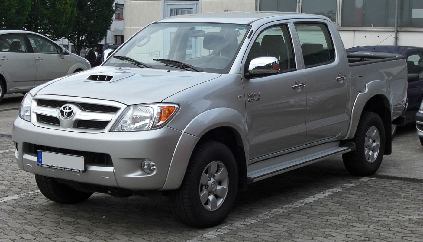
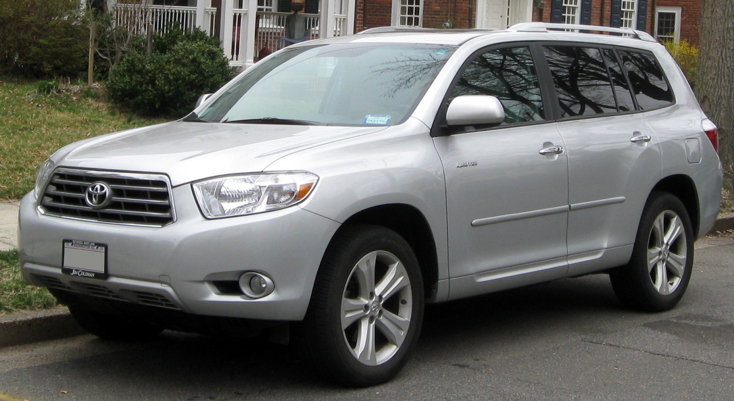
By M 93 - Own work, CC BY-SA 3.0
Below you'll find the tightening torques for the Toyota Hilux 7 in both Nm and ft/lbs. The first table contains the most-used torque settings. The tables after it contain all torque spec values I could find.
Most-used torque specs for Toyota Hilux 7
| Part | Description | Torque (Nm) | Torque (ft/lbs) | Remarks | Applies to | |
|---|---|---|---|---|---|---|
| Transmission fluid pan | Drain plug | 20 | 15 |
|
|
|
| Wheels | Front wheel | 152 | 112 | Steel type |
|
|
| Wheels | Front wheel | 132 | 97 | Aluminium type |
|
|
| Wheels | Front wheel | 105 | 77 |
|
|
|
| Wheels | Rear wheel | 152 | 112 | Steel type |
|
|
| Wheels | Rear wheel | 121 | 89 | Aluminium type |
|
|
| Wheels | Rear wheel | 105 | 77 |
|
|
To make sure these are the correct tightening torque values, you can use the data below to verify this is the right model.
Are these torque settings right for you?
- Production years: 2004 - 2015
- Generation: 7
- Type of van: pickup
- Model variant: Base
- Also known as:
All Torque Settings in Tables
engine torque settings
Save to email ✉️| Part | Description | Torque (Nm) | Torque (ft/lbs) | Remarks | Applies to | |
|---|---|---|---|---|---|---|
| Oil pan | Oil pan to Cylinder block | 16 | 12 |
|
|
|
| Oil pan | Oil pan to Timing gear case | 16 | 12 |
|
|
|
| Oil filter | Oil strainer to Oil pan subassembly | 8 | 6 |
|
|
|
| Oil filter | Oil strainer to Cylinder block | 8 | 6 |
|
|
|
| Oil dipstick | Oil level gauge guide to Intake manifold | 8 | 6 |
|
|
|
| Oil dipstick | Oil level gauge guide to Injection pipe clamp | 5 | 4 |
|
|
|
| Vacuum pump | Vacuum pump to Timing gear case cover | 21 | 15 |
|
|
|
| Piston rods | Connecting rod cap to Connecting rod | 35 | 26 | Stage 1 |
|
|
| Cylinder head | Cylinder head to Cylinder block | 85 | 63 | Stage 1 |
|
|
| Cylinder head | Water inlet to Cylinder head | 19 | 14 |
|
|
|
| Cylinder head | Water hose clamp to Cylinder head | 18 | 13 |
|
|
|
| Cylinder head | Cylinder head cover to Cylinder head | 9 | 7 |
|
|
|
| Glow plugs | Glow plug to Cylinder head | 13 | 10 |
|
|
|
| Glow plugs | Glow plug connector to Glow plug nut | 2 | 1 |
|
|
|
| Intake manifold | Intake manifold to Cylinder head | 29 | 21 |
|
|
|
| Intake manifold | Manifold stay to Intake manifold | 19 | 14 |
|
|
|
| Throttle body | Diesel throttle body assembly to Intake air connector | 20 | 15 |
|
|
|
| Throttle body | Diesel throttle body bracket to Intake air connector | 20 | 15 |
|
|
|
| Throttle body | Diesel throttle body bracket to Intake manifold | 20 | 15 |
|
|
|
| Engine block | Cylinder block drain cock plug to Oil cooler cover subassembly | 8 | 6 |
|
|
|
| Engine block | Engine rear oil seal retainer to Cylinder block | 13 | 10 | Bolt A |
|
|
| Engine block | Engine rear oil seal retainer to Cylinder block | 16 | 12 | Bolt B |
|
|
| Engine block | Oil check valve subassembly to Cylinder block | 26 | 19 |
|
|
|
| Engine block | Manifold stay to Cylinder block | 19 | 14 |
|
|
|
| Engine block | Compressor mounting block no.1 to Cylinder block | 47 | 35 |
|
|
|
| Engine block | Rear end plate to Cylinder block | 8 | 6 |
|
|
|
| Engine block | Water inlet to Cylinder block | 13 | 10 |
|
|
|
| Engine mounts | Engine mounting bracket to Cylinder block | 68 | 50 |
|
|
|
| Engine mounts | Engine mounting bracket to Body | 38 | 28 |
|
|
|
| Engine mounts | Engine cover subassembly to Charge air cooler assembly with intake air connector | 7 | 5 |
|
|
|
| Sensor | Camshaft position sensor to Timing gear case | 9 | 7 |
|
|
|
| Sensor | Crankshaft position sensor to Timing gear case | 9 | 7 |
|
|
|
| Sensor | Engine coolant temperature sensor to Cylinder head | 20 | 15 |
|
|
|
| Sensor | Engine oil level sensor to Oil pan | 8 | 6 |
|
|
|
| Sensor | IAT sensor to Charge air cooler | 29 | 21 |
|
|
|
| Sensor | Manifold absolute pressure sensor to Charge air cooler | 6 | 4 |
|
|
|
| Alternator | Generator to V-ribbed belt tensioner | 62 | 46 | Bolt A |
|
|
| Alternator | Generator to V-ribbed belt tensioner | 25 | 18 | Bolt B |
|
|
| Alternator | Generator bracket to Generator assembly | 25 | 18 |
|
|
|
| Alternator | Generator bracket to Timing gear case cover | 25 | 18 |
|
|
|
| Alternator | Generator wire to Generator | 6 | 4 |
|
|
|
| Starter | Starter assembly to Transmission housing | 68 | 50 |
|
|
|
| Starter | Starter assembly to Manual transmission unit assembly | 68 | 50 |
|
|
|
| Starter | Starter assembly to Manual transmission unit assembly | 68 | 50 |
|
|
|
| Starter | Terminal 30 to Starter assembly | 10 | 7 |
|
|
|
| Starter | Terminal C to Starter assembly | 6 | 4 |
|
|
|
| Camshaft | Camshaft bearing cap to Cylinder head | 19 | 14 |
|
|
|
| Camshaft | Camshaft timing pulley to Camshaft | 98 | 72 |
|
|
|
| Camshaft | Camshaft timing pulley flange no.2 to Pump drive shaft pulley | 31 | 23 |
|
|
|
| Crankshaft | Crankshaft bearing cap to Cylinder block | 50 | 37 | Stage 1 |
|
|
| Crankshaft | Crankshaft pulley to Crankshaft | 365 | 269 |
|
|
|
| Crankshaft | Crankshaft timing pulley flange no.2 to Pump drive shaft pulley | 31 | 23 |
|
|
|
| Crankshaft | Driven gear to Balance shaft subassembly | 36 | 27 |
|
|
|
| Common rail | Common rail assembly to Cylinder block | 38 | 28 |
|
|
|
| Common rail | Fuel pipe to Injector and common rail | 35 | 26 |
|
|
|
| Common rail | Fuel inlet pipe to Common rail and supply pump | 35 | 26 |
|
|
|
| Water pump | Water pump assembly to Cylinder block | 13 | 10 |
|
|
|
| Water pump | Cooling fan to Water pump assembly | 18 | 13 |
|
|
|
| Water pump | No.1 automatic transmission to Water pump inlet | 13 | 10 |
|
|
|
| Fuel/Oil cooler | Oil cooler assembly to Oil cooler cover subassembly | 16 | 12 |
|
|
|
| Fuel/Oil cooler | Oil cooler subassembly to Cylinder block | 13 | 10 |
|
|
|
| Intercooler | Intake air connector to Charge air cooler | 10 | 7 |
|
|
|
| Intercooler | Charge air cooler to Stay | 12 | 9 |
|
|
|
| Intercooler | Charge air cooler to Intake manifold | 32 | 24 |
|
|
|
| Intercooler | No.1 gas filter to Charge air cooler | 6 | 4 |
|
|
|
| Radiator | Radiator assembly to Body panel | 12 | 9 |
|
|
|
| Radiator | Oil reservoir to Radiator tank upper | 5 | 4 |
|
|
|
| Radiator | Radiator reservoir to Radiator assembly | 5 | 4 |
|
|
|
| Radiator | Vent plug to Radiator tank upper | 2 | 1 |
|
|
|
| Radiator | Fan shroud to Radiator tank upper | 5 | 4 |
|
|
|
| Air conditioning | Cooler compressor assembly to Compressor mounting bracket no.1 | 50 | 37 |
|
|
|
| Air conditioning | Cooler compressor assembly to Engine | 25 | 18 |
|
|
|
| Belt tensioner/Timing chains | Timing belt tensioner to Cylinder block | 13 | 10 |
|
|
|
| Belt tensioner/Timing chains | Timing belt tensioner to Timing gear case | 13 | 10 |
|
|
|
| Belt tensioner/Timing chains | Timing belt idler pulley to Cylinder block | 35 | 26 |
|
|
|
| Belt tensioner/Timing chains | Timing belt no.1 cover to Timing belt no.2 cover | 6 | 4 |
|
|
|
| Belt tensioner/Timing chains | Vane pump to Timing gear case | 39 | 29 |
|
|
|
| Belt tensioner/Timing chains | V-ribbed belt tensioner assembly to Cylinder block | 21 | 15 |
|
|
|
| Belt tensioner/Timing chains | V-ribbed belt tensioner assembly to Water pump assembly | 21 | 15 |
|
|
|
| Fuel system | Fuel tank band subassembly no.1 to Body | 61 | 45 |
|
|
|
| Fuel system | Fuel tank vent tube subassembly to Fuel tank assembly | 2 | 1 |
|
|
|
| Fuel system | Fuel tank filler pipe subassembly to Body | 19 | 14 |
|
|
|
| Fuel system | Fuel pipe clamp no.2 to Fuel pipe | 5 | 4 |
|
|
|
| Fuel system | Fuel pipe clamp no.3 to Fuel pipe | 5 | 4 |
|
|
|
| Fuel system | Fuel inlet pipe clamp | 5 | 4 |
|
|
drivetrain torque settings
Save to email ✉️| Part | Description | Torque (Nm) | Torque (ft/lbs) | Remarks | Applies to | |
|---|---|---|---|---|---|---|
| Clutch assembly | Clutch release cylinder to Manual transmission unit assembly | 12 | 9 |
|
|
|
| Transmission mount/case | Stiffener assembly to Manual transmission unit assembly | 72 | 53 |
|
|
|
| Transmission mount/case | Stiffener assembly to Manual transmission unit assembly | 72 | 53 |
|
|
steering torque settings
Save to email ✉️| Part | Description | Torque (Nm) | Torque (ft/lbs) | Remarks | Applies to | |
|---|---|---|---|---|---|---|
| Power steering | Power steering vane pump housing rear to Vane pump housing front | 22 | 16 |
|
|
|
| Power steering | Power steering vane pump assembly to Engine | 39 | 29 |
|
|
|
| Power steering | Pressure feed tube assembly to Vane pump assembly | 40 | 30 | For use without SST |
|
|
| Power steering | Pressure feed tube assembly to Vane pump assembly | 44 | 32 | For use with SST |
|
|
exhaust torque settings
Save to email ✉️| Part | Description | Torque (Nm) | Torque (ft/lbs) | Remarks | Applies to | |
|---|---|---|---|---|---|---|
| Exhaust manifold | Exhaust manifold to Cylinder head | 40 | 30 |
|
|
|
| Exhaust manifold | Exhaust manifold heat insulator to Exhaust manifold | 12 | 9 |
|
|
|
| Exhaust manifold | Front exhaust pipe assembly to Outlet pipe | 43 | 32 |
|
|
|
| Exhaust manifold | Center exhaust pipe assembly to Front exhaust pipe assembly | 48 | 35 |
|
|
|
| Exhaust manifold | Tailpipe assembly to Center exhaust pipe assembly | 48 | 35 |
|
|
|
| Turbo | Turbocharger to Exhaust manifold | 52 | 38 |
|
|
|
| Turbo | Turbo oil inlet pipe subassembly to Turbocharger | 13 | 10 |
|
|
|
| Turbo | Turbo oil inlet pipe subassembly to Cylinder block bolt | 12 | 9 |
|
|
|
| Turbo | Turbo oil inlet pipe subassembly to Cylinder block union bolt | 26 | 19 |
|
|
|
| Turbo | Turbocharger stay to Turbocharger | 24 | 18 |
|
|
|
| Turbo | Turbocharger stay to Cylinder block | 24 | 18 |
|
|
|
| Turbo | No.1 turbo insulator to Turbocharger | 12 | 9 |
|
|
|
| Turbo | Compressor inlet elbow to Turbocharger | 19 | 14 |
|
|
|
| Turbo | Turbine outlet elbow to Turbocharger | 26 | 19 |
|
|
|
| EGR | No.1 EGR pipe subassembly to EGR valve | 19 | 14 |
|
|
|
| EGR | No.1 EGR pipe subassembly to Cylinder head | 19 | 14 |
|
|
|
| Muffler | Main muffler heat insulator to Body | 5 | 4 |
|
|
brakes torque settings
Save to email ✉️| Part | Description | Torque (Nm) | Torque (ft/lbs) | Remarks | Applies to | |
|---|---|---|---|---|---|---|
| Brake pedal | Accelerator pedal rod assembly to Body | 5 | 4 |
|
|
suspension torque settings
Save to email ✉️| Part | Description | Torque (Nm) | Torque (ft/lbs) | Remarks | Applies to |
|---|
general torque settings
Save to email ✉️| Part | Description | Torque (Nm) | Torque (ft/lbs) | Remarks | Applies to |
|---|
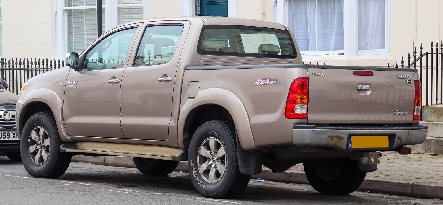
By Vauxford - Own work, CC BY-SA 4.0
Did you find the answer to your specific question?
👍 5 👎 5
